Do you have a carbureted V8? The DLG-1, or dual lambda gauge, could be your best friend by monitoring both sides of the engine. Check out our install on a Fairlane.
An engine relies on two things to run: spark and fuel. Sure, there are a million other things to consider when speaking of engine operation and power, but regardless of the type, size, or brand of engine, it has to have spark and fuel. (Diesel engines are an exception since their combustion comes via compression, not a spark generated by an ignition system).

Originally featured in Mustang Monthly.
To learn more about the DLG-1 gauge, click here.
When it comes to the fuel half of the equation, fuel and air are combined to generate a ratio of air to fuel ratio, often abbreviated as AFR. In any discussion of engine tuning, the AFR is one of the main topics. The AFR defines the ratio of the amount of air consumed by the engine compared to the amount of fuel, and proper AFR calibration is critical to performance and durability of the engine and its components.

A “stoichiometric” AFR has the correct amount of air and fuel to produce a chemically complete combustion event. By definition, stoichiometric is the calculation of relative quantities of reactants and products in chemical reactions. Which is a fancy way of saying it’s a mathematically derived “ideal” ratio of air to fuel. For gasoline engines, the stoichiometric AFR is 14.7:1, which means 14.7 parts of air to one part of fuel.
The stoichiometric AFR depends on fuel type—for alcohol it is 6.4:1 and 14.5:1 for diesel. For the purposes of our conversation here, we’re just concerned with a gas-burning engine, so 14.7:1 is the ratio that lies in the middle of a “rich” or “lean” mixture. A lower AFR number contains less air than the 14.7:1 stoichiometric AFR, therefore it is a richer mixture. Conversely, a higher AFR number contains more air and therefore it is a leaner mixture.
For Example:
16.0:1 = Lean
14.7:1 = Stoichiometric
12.0:1 = Rich

Leaner AFR creates higher temperatures as the mixture burns. Generally, normally aspirated spark-ignition gasoline engines produce maximum power just slightly rich of stoichiometric. In practice it is usually kept between 12:1 and 13:1 in order to keep exhaust gas temperatures in check and to account for differences in fuel quality. A 12:1 AFR is generally considered to be about right on a gas engine under full load (wide open throttle, hooked up and haulin’ butt), though there are certainly exceptions depending on a million different things.
Sensor Calibration
In case you lost the instructions with your kit, here’s how to calibrate the oxygen sensors:
1) With the sensors disconnected, apply power to the DLG-1 and LC-2. Confirm that both channel A and B are reporting an E2 error code, indicating that no sensor is detected. Leave unit powered on for a minimum of 30 seconds.
2) Power down the DLG-1 and LC-2 and attach the oxygen sensors using the cable provided. When making these connections, make sure they are fully seated and locked. Again, make sure that the sensors are in free air (not in the exhaust).
3) Power up the DLG-1 and LC-2.The gauge will show that the sensors are warming up, this is indicated by “HTR.” After 30-60 seconds, the display will switch from “HTR” and quickly flash “CAL”, indicating that the sensor is being calibrated.
The calibration procedure has completed and the system is now ready for use.
Important: You can disconnect and reconnect the sensor and sensor cable for installation without losing your calibration. However, if you power up the DLG-1 or LC-2 without a sensor connected, your calibration will be reset (see step #1 above).
Calibration Schedule
Normally aspirated daily driver:
– Calibrate before installation of new sensor
– Calibrate new sensor again after 3 month of use
– Thereafter calibrate once a year or every 20,000 miles, whichever comes first
Turbo car, daily driver (richer mixture):
– Calibrate before installation of new sensor
– Calibrate new sensor again after 3 month of use
– Thereafter calibrate twice a year or every 10,000 miles, whichever comes first
Race car
– Calibrate before first installation of new sensor
– Calibrate once per race weekend

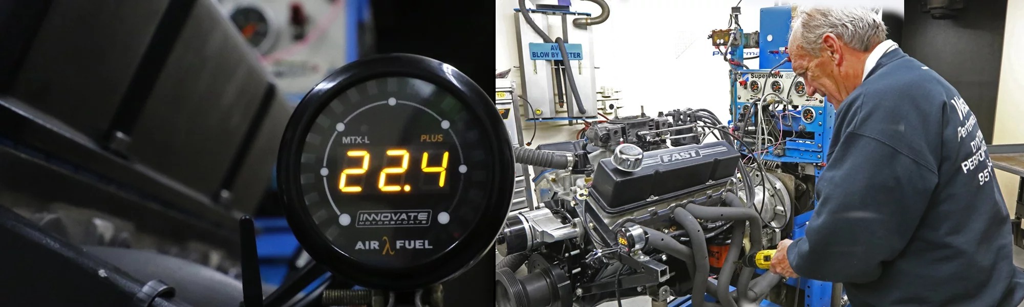
Electronic fuel-injected engines allow precise control over AFR, whereas a carburetor is more primitive—the AFR depends on air flow and carb jetting, basically. Once it’s set, your AFR is what it is until you readjust the carburetor. Because of this, an air fuel ratio gauge, such as the Innovate DLG-1 we’re installing in this story, is a fantastic tuning tool to tell you where your AFR is and how it changes over different rpm and load. Without an air fuel ratio gauge, the only way to tell what your AFR is, is to “read” the spark plugs. An overly rich mixture will also burn your eyes and nose with the exhaust gas, but that’s hardly precise.
Innovate has several types of air/fuel ratio gauges as part of its Modular Tuning System (MTS). As the company’s own website explains, “All Innovate products are completely modular, enabling you to build the perfect tuning system for your needs. The MTS is scalable, and all components share a common digital communications protocol. A simple and common configuration is an MTX-L PLUS gauge for A/F monitoring. A more complex setup might include an LC-2 on every cylinder, a LM-2 for recording, two TC-4 PLUSs for exhaust gas temperature (or CHT), an AuxBox (LMA-3) for intake and turbo temp, speedo and TPS, and lastly an MTX-L PLUS to monitor the data in real-time.”

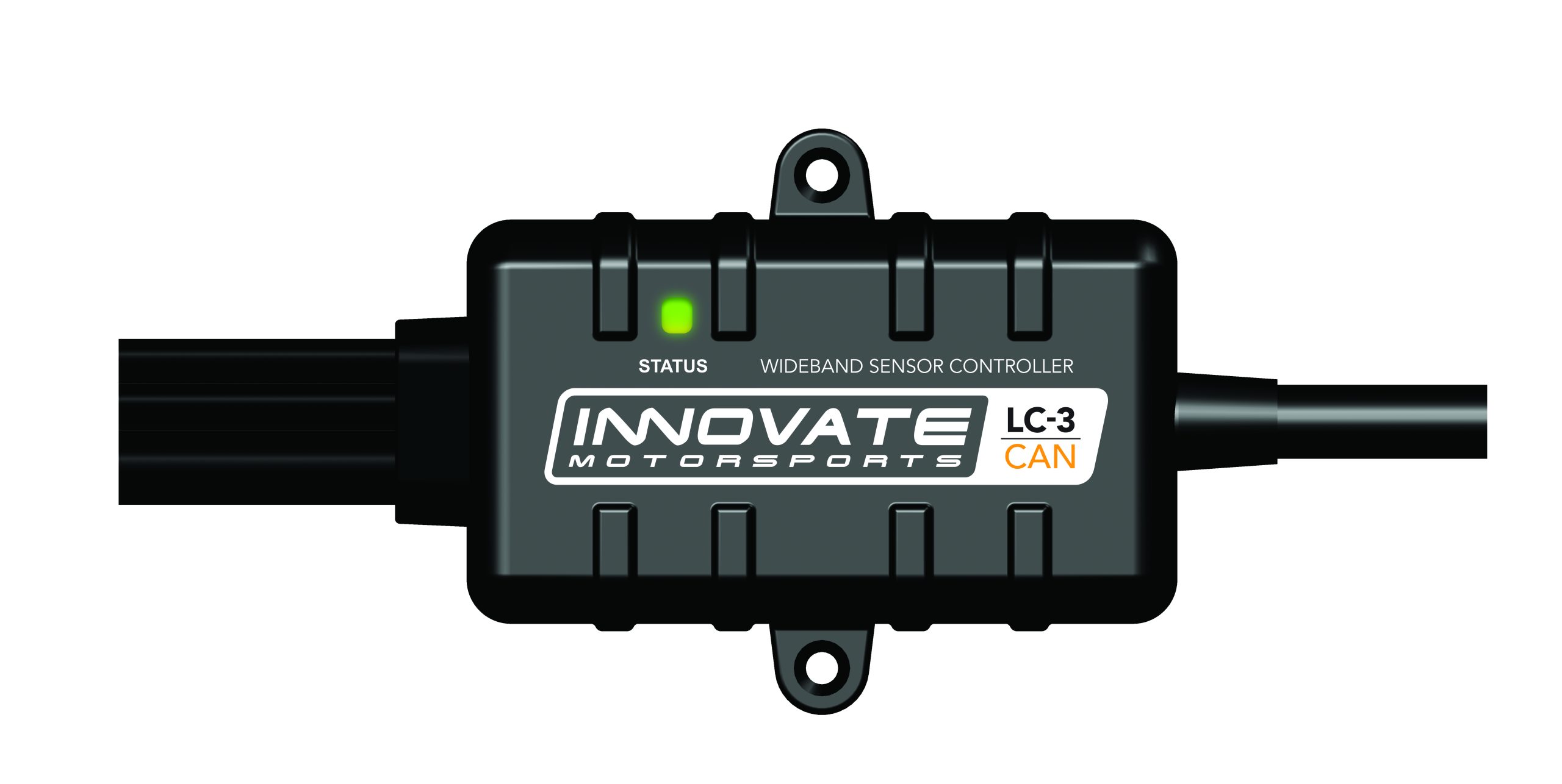
For the sake of simplicity in this story, we’re going to install a DLG-1 digital air/fuel ratio gauge, with an optional LC-2 Digital Wideband “Lambda” 02 Controller, into a carbureted 351W-powered 1966 Fairlane. The DLG-1 by itself can read one input from an oxygen sensor installed in the exhaust system—adding the LC-2 allows us to use a second sensor in the other side of the exhaust so we can read both banks of the engine through a single gauge. (Normally, the AFR should be roughly identical between the left and right banks, but variations do occur, and a radical difference in ratios with use can point to a problem, like a dead cylinder, poor mixture distribution—poorly designed intake manifold or very leaky exhaust manifold/header—and other maladies).
Installation is fairly easy and straightforward. The DLG-1 Dual Lambda (AFR) Gauge Kit (part no. 3891) includes the DLG-1 gauge, two wideband Bosch LSU4.9 O2 sensors, two 8-foot sensor cables, LC-2 Wideband Controller, two O2 sensor weld-on bungs, black/silver bezel, black/white faceplate, serial program cable, and installation manual.

Gauge Features:
| • Monitor left and right exhaust banks on one single gauge
• Perfect for all V configured engines • Plug & Play setup for both O2 sensors • No PC required for additional configuration • 52mm (2 1/16”) diameter gauge body • Interchangeable faceplates and bezels: Black and silver bezel, black and white faceplates included • User configurable OLED display (AFR or Lambda) • Multiple ways to display data on gauge • Patented DirectDigital™ wideband sensor control, 100% digital wideband air/fuel ratio technology! • Wideband O2 Compatible with several fuel types (Leaded, Unleaded, Diesel, E85 & more) • Ability to calibrate O2 sensors for maximum accuracy • Configurable linear 0-5v analog output for wideband O² for use with piggy back or stand alone ECUs as well as external data loggers • Innovate MTS serial in/out (for use with other Innovate and 3rd party MTS-enabled devices to add additional logging channels) • Datalog both O2 channels using powerful LogWorks software on a PC |